Reliable solutions in energy distribution




Products
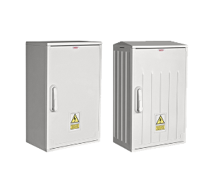
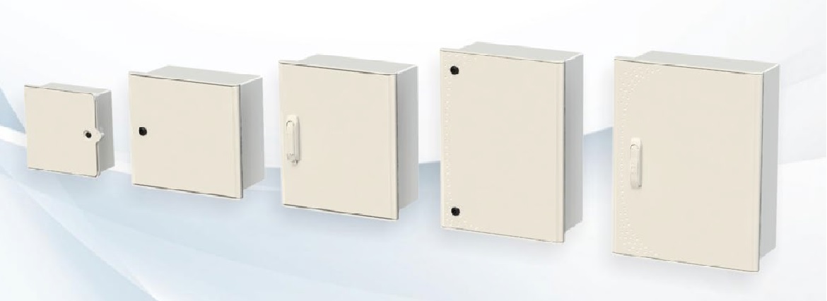
Polyester cabinets

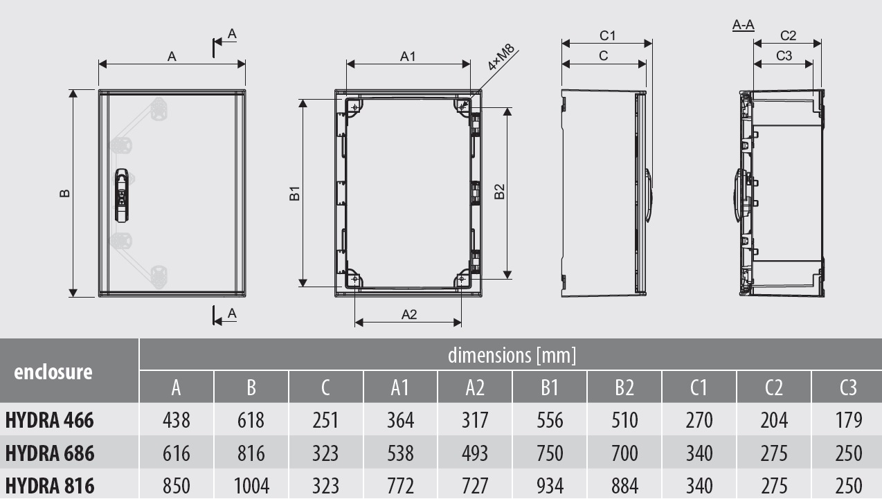
Tight enclosures HYDRA (IP65 / IP66)
Tight Enclosures HYDRA are applicable, among others, in the energy sector, automation, telecom-munication industry, and especially in places with a large extent of contamination and also places exposed to flooding (production plants, waste water treatment plants, coastal area). Specially designed construction of the enclosure provides effective protection of internal devices against the negative influence of external factors (dust, corrosive fumes, water).
Basic parameters:
| Temperature operating conditions | -50oC +85oC |
| Flammability category | V0 |
| Protection class | II |
| Material | halogen-free material |
| Colour | RAL 7035 |
| Impact resistance | IK10 |
HYDRA enclosures are made of glass fiber rein-forced polyester, they are corrosion resistant aga-inst the impact of chemicals and solvents.Enclosures HYDRA are available in two versions, depending on the degree of protection IP:
• IP65 with 2-point locking system with 2 locks;
• IP66 – equipped with 4-point locking system, which includes: tight lock ZIP66, rod and lo-cking elements, arranged on the perimeter.
The doors of enclosure are equipped with polyu-rethane gasket. It is possible to reverse the door (left/right).


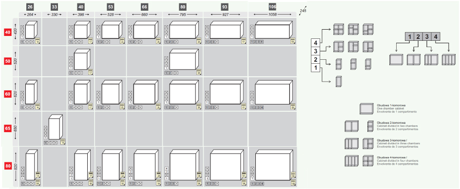
Cabinets OS, OSZ, OSi, OSZi - depth: 245 mm
The enclosures of the OS and OSZ series cabinets (depth 245 mm) are widely used in industry, energy and telecommunications due to their universal design. The cabinets are made of insulating, flame retardant and self-extinguishing composite (polyester + fiberglass), which is UV resistant.
Cabinets are designed for indoor and outdoor installation regardless of the roof type (inclined, flat).
Two types of outer surface (OSZ ribbed, “anti-poster”, OS smooth) allow you to choose the case depending on the operating conditions. The ventilation system minimizes the possibility of moisture accumulation.
The foundation walls can be removed without the use of tools, making it easy to insert cables into the installed cabinet. A specially developed housing design in combination with additional elements ensures quick and convenient equipment installation. The modularity of the design makes it possible to combine the enclosure with a foundation and / or cable section, and also allows enclosures to be connected vertically.
Enclosures with insulators – 245mm depth – OSi, OSZi
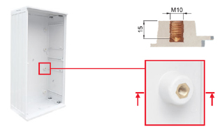
Housings of cabinets of the OSi and OSZi series (depth 245 mm) are designed for the installation of a busbar system and switching equipment. Insulators built into the rear of the enclosure ensure stable installation and standard busbar spacing (185 mm spacing). The design of the threaded bush (screw thread M 10) protects against screwing in too long bolts / screws.
Types of the outer surface of the enclosures:
- OSi – smooth surface,
- OSZi is a ribbed surface.
The cabinets are designed for indoor and outdoor installation, regardless of the type of roof (inclined, flat). The modularity of the structure makes it possible to combine the housing with a foundation or / and with a section for cables, as well as to combine enclosures from different standard series (e.g. OSZi + OSZ). The ventilation system minimizes the possibility of moisture accumulation. The foundation walls can be removed without the use of tools, making it easy to insert cables into the installed cabinet.
Main settings:
| degree of protection | IP44 ,IP54- option |
| impact resistance | IK10 |
| body depth | 245mm |
| insulation voltage | AC 690V |
| operating temperature | -50°C; +85°C |
| fire resistance class | V0 |
| color | RAL 7035 |
| protection class | II |
| compare tracking index | CTI 600 |
| dielectric strength | 22 kV/mm |
| resistivity | 10^14Ωcm |
| according to European standard | EN 61 439-1 EN 61 439-3 EN 61 439-5 EN 62 208 |
Cabinets KS, KSZ, KSi, KSZi - depth: 320 mm
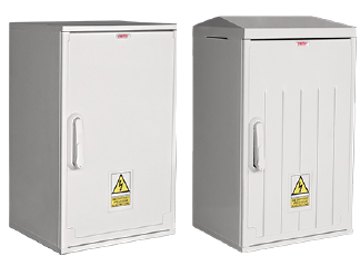
Cabinets are made of insulating, flame retardant and self-extinguishing composite (polyester + fiberglass), UV resistant
Two types of surface:
- KS – completely smooth body,
- SZ – ribbed surface (door and back wall).
Two types of roofs allow you to choose the body depending on the operating conditions. The ventilation system minimizes the possibility of moisture accumulation. The foundation walls can be removed without the use of tools, making it easy to insert cables into the installed cabinet.
The specially developed design of the housing, in combination with additional elements, provides a quick and convenient installation of equipment. The modular design makes it possible to connect the enclosure to the foundation and / or cable section, and also allows the enclosures to be connected vertically.
Main settings:
| degree of protection | IP44 ,IP54- option |
| impact resistance | IK10 |
| body depth | 320mm |
| insulation voltage | AC 690V |
| operating temperature | -50°C; +85°C |
| fire resistance class | V0 |
| color | RAL 7035 |
| protection class | II |
| compare tracking index | CTI 600 |
| dielectric strength | 22 kV/mm |
| resistivity | 10^14Ωcm |
| according to European standard | EN 61 439-1 EN 61 439-3 EN 61 439-5 EN 62 208 |

Enclosures – depth 320 mm – with insulators – KSi, KSZi
The enclosures of the KSi and KSZi type cabinets (depth 320 mm) are designed for the installation of a busbar system and switching equipment. Insulators built into the back of the enclosure ensure stable installation and standard busbar spacing (185mm pitch). The design of the threaded bush (screw thread M10) protects against screwing in too long bolts / screws.
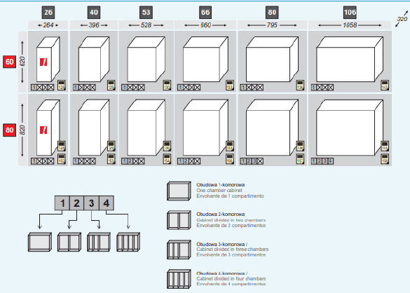
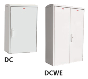
Cabinets DC, DCB, DCWE, DCWEB (DIN) - depth: 320 mm
Enclosures DC, DCB, DCWE, DCWEB (depth 320 mm), due to their versatility, are widely used in industry, energy and telecommunications. Made of insulating, flame-retardant and self-extinguishing composite (polyester + fiberglass), UV resistant.
The ventilation system minimizes moisture build-up. The walls of the foundation can be dismantled without the use of tools, making it easier to enter the cables into the device. A well-thought-out design of the case, together with additional elements, ensures quick and high-quality installation of equipment.
The new type of enclosures DCB and DCWEB are equipped with a bottom, while the DC and DCWE enclosures are designed for installation on a foundation or a plinth (enclosure without a bottom).
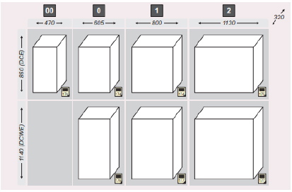
Main settings:
| degree of protection | IK10,IP44; IK10,IP54 |
| impact resistance | 860mm/1140mm |
| body depth | 320mm |
| insulation voltage | AC 690V |
| operating temperature | -50°C; +85°C |
| fire resistance class | V0 |
| color | RAL 7035 |
| protection class | II |
| compare tracking index | CTI 600 |
| dielectric strength | 240 kV/mm |
| resistivity | 10^14Ωcm |
| according to European standard | DIN 43 629-1 DIN 43 629-2 DIN 43 629-3 EN 61 439-1 EN 61 439-3 EN 61 439-5 EN 62 208 |
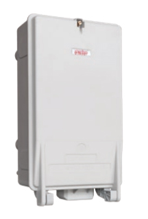

Cabinet KH 00 - depth: 138 mm
The casing type KH 00 is made of glass fiber reinforced polyester and consists of two elements: a casing and a door with an opening angle of 180 °.
Can be sealed. There is a cable entry at the bottom of the housing. Fuse bases and clamps of various types can be installed in the housing.
KH 00 enclosures with fuses up to 100A are used as connecting devices between the external electrical network and the consumer’s network, they can also be installed in cabinets as the main protection.
Main settings:
| degree of protection | IP54 |
| impact resistance | IK10 |
| insulation voltage | AC 500V |
| operating temperature | -50°C; +85°C |
| fire resistance class | V0 |
| color | RAL 7035 |
| protection class | II |
| compare tracking index | CTI 600 |
| dielectric strength | 220 kV/mm |
| resistivity | 10^14Ωcm |
| cross-sections of incoming – outgoing wires | 10re-95se mm2 – 10rm-70sm mm2 |
| according to European standard | DIN VDE 0660-505: 1998-10 DIN 43627 |


Cabinets OW, OWG - depth: 214 mm
Housings type OW, OWG are made of insulating, flame retardant and self-extinguishing composite (polyester + glass fiber), resistant to UV radiation. Designed for wall and pole mounting (+ u).
Two-piece construction (body + door) shortens assembly time. The enclosure meets the requirements for enclosures for indoor installation. OW enclosures are available in two door options: ribbed (OW) anti-poster and smooth (OWG).
OWi and OWGi enclosures are equipped with isolators to facilitate installation. The insulators are built into the back of the enclosure, thus ensuring a robust installation. The design of the threaded bush (M8) prevents over-long bolts from being screwed in.
Main settings:
| degree of protection | IP44 |
| impact resistance | IK10 |
| body depth | 214mm (OW,OWG) |
| insulation voltage | AC 690V |
| operating temperature | -50°C +85°C |
| fire resistance class | V0 |
| color | RAL 7035 |
| protection class | II |
| compare tracking index | CTI 600 |
| dielectric strength | 22 kV/mm |
| resistivity | 1014Ωcm |
| according to European standard | EN 61 439-1 EN 61 439-5 EN 61 439-5 EN 62 208 |


Cabinets LILA
The enclosures of the LILA series are made of an insulating, flame-resistant and self-extinguishing composite (polyester + glass fiber), UV-resistant.
Designed for installation in a wall or on a pole (LILA + u and LILA S + U for which a pole mount kit with a 19 mm wide metal strip is provided).
The housings are equipped with insulators with M6 threaded bushings to facilitate equipment installation. The insulators are built into the back of the enclosure, thus ensuring a robust installation.
Depending on the type of housing, they have a different locking method: lock type 1022-U66 with a universal key or bolt M5 × 16. In addition, a hole is provided in the body and doors for installing a seal.
Main settings:
| degree of protection | IP44/IP54/IP65/IP66 |
| impact resistance | IK10 |
| insulation voltage | AC 690V |
| operating temperature | -50°C +85°C |
| fire resistance class | V0 |
| color | RAL 7035 |
| protection class | II |
| compare tracking index | CTI 600 |
| dielectric strength | 22 kV/mm |
| resistivity | 1014Ωcm |
| according to European standard | EN 61 439-1 EN 61 439-3 EN 61 439-5 EN 62 208 |


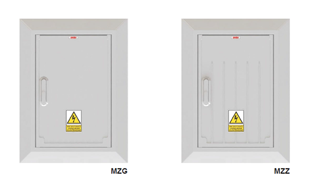
Masking frames MZG, MZZ
Decorative panels type MZZ, MZG consist of a frame and a door made of glass fiber reinforced polyester.
They can be used to close openings, niches in the wall of a building or to modernize old switchgears.
MZG – smooth decorative panel doors MZZ – ribbed decorative panel doors
Main settings:
| degree of protection | IK10, IP44 |
| insulation voltage | AC 500V |
| operating temperature | -50°C +85°C |
| fire resistance class | V0 |
| color | RAL 7035 |
| protection class | II |
| compare tracking index | CTI 600 |
| dielectric strength | 22 kV/mm |
| resistivity | 1014Ωcm |
| according to European standard | EN 61 439-1 EN 61 439-3 EN 61 439-5 EN 62 208 |
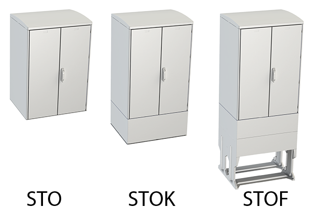
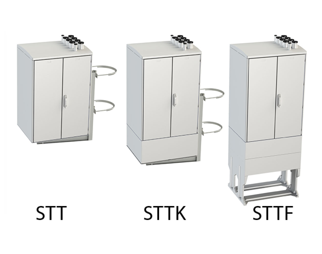

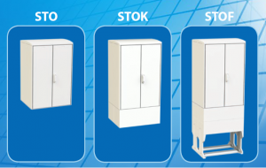
Cabinets STT, STTK, STTF, STO, STOK, STOF - depth: 640 mm
STT • STTK • STTF • STO • STOK • STOF
Glass fiber reinforced polyester enclosures.
The front and back of the cabinet has a door with a 3-point closing system.
Option – opening from 1 side only.
The chassis comes in four basic configurations:
- STT – housing is designed for the assembly of switchgear transformers, a roof with pipes for cable entry and a platform with a clamp for mounting on a pole; the system of insulators allows the installation of rack and pinion equipment (fed from below or from above); the possibility of installing a cable channel in the lower part of the case;
- STTK – the housing is intended for the assembly of switchgear transformer devices. Thanks to the polyester cable section, we get additional installation space for devices with non-standard dimensions, as well as comfort when connecting cables;
- STTF – the housing is designed for the assembly of switchgear transformers, has a polyester base, which ensures stable installation of the switchgear in
- STO – universal housing with the ability to mount on cable sections; the system of insulators allows the installation of rack and pinion equipment and other electrical devices of large dimensions using various types of support elements (mounting panels, corners, etc.);
- STOK – universal casing with cable section;
- STOF is a universal case with a foundation.
Main settings:
| degree of protection | IP44 |
| impact resistance | IK10 |
| body depth | 245mm |
| insulation voltage | AC 690V |
| operating temperature | -50°C +85°C |
| fire resistance class | V0 |
| color | RAL 7035 |
| protection class | II |
| compare tracking index | CTI 600 |
| dielectric strength | 22 kV/mm |
| resistivity | 1014Ωcm |
| according to European standard | PN-EN 62208-2006 PN-EN 60529-2003 PN-EN 62262-2003 PN-EN 50274-2004 PN-EN 61439-1:2010 PN-EN 61439-2:2010 |
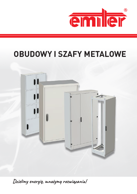
Emiter metal cabinerts

SSS Tight control cabinets IP65 / IP66
Tight control cabinets, depending on mounted equipment, can be used for low voltage switchgears building, control cabinets for supervision of production processes.
Construction:
- Materiał: AZ150 Aluzinc steel sheet,
- Elements connected by means of riveting, screwing and welding,
- Single door for a cabinet width less than or equal to 1000 mm,
- Double door for a cabinet width greater than 1000mm,
- EPDM gasket applied to the edge of the cabinet,
- Flat roof,
- Slope roof (optional equipment),
- Roof and base with a notch enabling cable glands mounting,
- 3-point lever lock for patented locking cylinder,
- Cabinets, socles and roofs powder coated.
Features:
- Corrosion resistance,
- Back wall and sides perforations for mounting equipment on any height and depth,
- Dierent types of socles enables placing on dierent surfaces.
Basic parameters:
| Impact resistance | IK10 |
| Protection rating | IP 55 |
| Protection class | I |
| Colour | RAL 7035 |
Installation method:
- C10 – on socles h=100mm,
- CW – non free-standing socles with a inspection panel, h=400mm,
- CZ – on socles designed to put in the ground, h=900mm,
- CW+CZ – on socles designed to put in the ground with inspection panel, h=1300mm,
Operating conditions:
- W – indoors,
- Z – outside.
Optional equipment:
- Mounting plates,
- Socles,
- Cable gland plates,
- Slope roof.


OMU Universal wall mounted enclosures IP31
Indoor enclosures for switchgears, control devices for processes and machines.
Konstrukcja:
- material made of carbon steel sheet,
- recessed doors mounted on hinges,
- standard cabinet without back panels,
- mounting holes on the back wall,
- key lock 1333 (cabinet height lower than or equal to 80), lever lock with locking cylinder (cabinet height greater than 80),
- powder coating.
Installation method:
- N – surface mounted,
- P – flush mounted,
- C – freestanding on a socles.
Condition of use:
- indoors in a dry environment.
Basic parameters:
| Impact resistance | IK10 |
| Protection rating | IP 31 |
| Protection class | I |
| Colour | RAL 7035 |
Basic equipment:
- key lock 1333.
Optional equipment:
- P – mounting plate,
- ZM – modular construction,
- cable gland plates – rear cover,
- C20 – freestanding socles,
- wall brackets,
- accessories.

OMS Universal tight enclosures IP65
Enclosures for electrical switchboards, control devices for production processes and machines.
Construction:
- carbon steel sheet DC01 for indoor enclosures,
- AZ150 Aluzinc steel sheet for outdoor enclosures,
- corpus welded (W) or riveted (Z),
- single door with a machine molded polyurethane (PUR) gasket. Hinged doors can be installed on the left and right side,
- one-point lock for key D5,
- mounting holes on the back wall,
- threaded bolts for the assembly of metal equipment,
- powder coating.
Installation method:
- N-wall mounted;
- CW- 400mm height freestanding socle with a inspection panel,
- CZ- 900mm socle designed to be put in the ground with a inspection panel.
Operating conditions:
- indoor in a dry environment,
- outdoor – wet and more agressive environment.
Basic parameters:
| Impact resistance | IK10 |
| Protection rating | IP 65 |
| Protection class | I |
| Colour | RAL 7035 |
Basic equipment:
- key lock 1333.
Optional equipment:
- P – mounting plate,
- ZM – modular construction,
- PPK – cable gland plates,
- CW – freestanding socle,
- CZ – socle designed to be burried in the ground,
- DJ – slope roof.

OHS Hygienic cabinets IP66
The hygienic enclosure OHS is intended for the installation of electrical equipment in food, pharmaceutical and cosmetics industry.
Construction:
- material: V2A stainless steel sheet (1.4301) or V4A acid-proof steel polished (1.4404),
- doors mounted on internal hinges, equipped with a silicone gasket,
- the ability to put the hinges on the left side,
- 2-point locking system,
- IP69K stainless steel locks – FDA compliant sealing,
- 2-element construction (body + door).
Operating indoorsi:
- indoors in humid and agressive environments
Features:
- Corrosion resistant cabinet (caused by water, steam, air moisture, food acids, organic and non organic acids, cleaning and disinfecting agents) as well as the eects of temperatures,
- the cabinet has no gaps in which dirt and bacteria may cumulate,
- slope roof prevents accumulation of dust and dirt on the top,
- surface of the cabinet and make cleaning much easier
- front edge of the roof protects the upper part of the gasket against dirt,
- tightness,
- hygienic,
- non – toxic,
- no maintenance required,
- permanent,
- smooth surfaces of the cabinet for easier cleaning.


Switchgear cabinets with measuring and area lighting compartments IP43
SK cabinets allow the assembly of control, distribution and measurement equipment. Cabinet and socle is made of aluminum alloy sheet ENAW 5754 with a thickness of 2,0mm . Elements are joined by riveting, screwing and welding.
Construction:
- single door for a cabinet width less than equal 850mm, double door for a cabinet width greater than 850mm,
- slope roof,
- 3-point lever lock for patented locking cylinder,
- CW free-standing socles equipped with control door,
- powder coated cabinets and socles.
Installation method:
- C10 on socles with a height equal to 100mm,
- CW on free-standing socles height equal to 400mm with a inspection panel,
- CZ on socles designed to put in the ground with inspection panel h=900mm,
- CW + CZ on socles designed to put in the ground with inspection panel,
- FZ on concrete pedestals
Basic parameters:
| Impact resistance | IK10 |
| Protection rating | IP 43 |
| Protection class | I |
| Colour | RAL 7035 |
Operating conditions:
- outside in an industrial amd seaside environment
Features:
- corrosion resistance,
- back wall and side perforations for mounting equipment on any hegiht and depth,
- dierent types of socles enables placing on dierent terrain.

SR Frame cabinets IP41, IP55
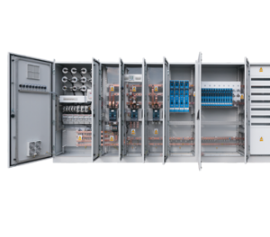
Frame cabinets, depending on the equipment installed in them, can be used for constructing LV switchgears, monitoring of electrical devices, supervision of production processes. The cabinets can be combined with each other in sets. The material of the cabinet and pedestal is made of carbon steel DC01.
Construction:
- components connected with each other by welding,
- single door for a width less than or equal to 1000mm,
- double doors for a width greater than 1000mm,
- 4-point lever lock for patented locking cylinder,
- powder coated cabinets and pedestals.
Operating conditions:
- W – inside in dry condition.
Features:
- possibility to connect cabinets in sets,
- perforated frame allows for easy assembly of equipment,
- selection of the degree of IP tightness depending on the cabinet operating conditions,
- removable side and rear panels provide free access to the interior of the cabinet.
Installation method:
- CR1 on socles with a height equal to 100mm.
Basic parameters:
| Impact resistance | IK10 |
| Protection rating | IP 41, IP 55 |
| Protection class | I |
| Colour | RAL 7035 |
- frame + door.
Optional equipment:
- BRW- internal side walls (IP41),
- BRZ- external side walls (IP55),
- PRW- internal back (IP 41),
- PRZ- external back (IP55),
- CR1- a socle with a height equal 100mm,
- CR2- a socle with a height of 200mm,
- K.KD,KG,KN- cable glands plates,
- P1- mounting plates,
- ZM- modular construction,
- DW- internal doors,
- NSR- corner cabinets.
SRN Frame cabinets IP30
Frame cabinets, depending on the equipment installed in them, can be used for constructing LV switchgears, monitoring of electrical devices, supervision of production processes or as network cabinets in telecommunications. The cabinets can be combined with each other in sets. One of them can serve as a supply field, other as outlet, next as measuring. Frame cabinets are made of AZ150 aluzinc steel sheet.
Construction:
- cabinet framework: it is made in the form of a frame consisting of vertical and horizontal profiles
- connected by a plastic corner,
- single door for a width less than or equal to 1000 mm,
- double door for a width greater than 1000mm,
- in the basic configuration, the doors are equipped with a 4-point closure,
- lever lock for patented locking cylinder,
- unpainted frame skeleton,
- powder coated covers, doors and pedestals.
Features:
- the ability to connect cabinets in sets,
- thanks to the use of aluzinc perforated frame profiles and one type of self-forming screws (M6), the mechanical structure is stable and enables any configuration of equipment assembly,
- removable covers ensure easy access to the interior of the cabinet.
Installation method:
- C10 – on socless h = 100mm (possibility of stacking).
Basic parameters:
| Resistance to mechanical impacts | IK10 |
| Degree of protection | IP 4X |
| Protection class | I |
| Colour | RAL 7035 |
Operating conditions:
- W – inside.
Basic equipment:
- frame,
- door.
Optional equipment:
- Side panels,
- Rear panels,
- Socles,
- Mounting plates,
- Brackets,
- Cable gland plates.

SSS Tight control cabinets IP65 / IP66
Tight control cabinets, depending on mounted equipment, can be used for low voltage switchgears building, control cabinets for supervision of production processes.
Construction:
- Materiał: AZ150 Aluzinc steel sheet,
- Elements connected by means of riveting, screwing and welding,
- Single door for a cabinet width less than or equal to 1000 mm,
- Double door for a cabinet width greater than 1000mm,
- EPDM gasket applied to the edge of the cabinet,
- Flat roof,
- Slope roof (optional equipment),
- Roof and base with a notch enabling cable glands mounting,
- 3-point lever lock for patented locking cylinder,
- Cabinets, socles and roofs powder coated.
Features:
- Corrosion resistance,
- Back wall and sides perforations for mounting equipment on any height and depth,
- Dierent types of socles enables placing on dierent surfaces.
Basic parameters:
| Impact resistance | IK10 |
| Protection rating | IP 55 |
| Protection class | I |
| Colour | RAL 7035 |
Installation method:
- C10 – on socles h=100mm,
- CW – non free-standing socles with a inspection panel, h=400mm,
- CZ – on socles designed to put in the ground, h=900mm,
- CW+CZ – on socles designed to put in the ground with inspection panel, h=1300mm,
Operating conditions:
- W – indoors,
- Z – outside.
Optional equipment:
- Mounting plates,
- Socles,
- Cable gland plates,
- Slope roof.

ORW Enclosures for free-standing switchgear IP30
Free-standing switchgear enclosures are designed for switchgears construction that are used for distribution and measurement of electricity in multi-family buildings. They are equipped with a set of power counter and modular fuses. They can be join in sets both free-standing and wall mounted.
Construction:
- 1.2mm thick carbon steelshaped by punching and bending joined by riveting and welding,
- powder coating,
- hinged doors with 3 point lock, LE40Ucz.
Installation method:
- C10- on socles height 100mm.
Features:
- corrosion resistance,
- Back wall and sides perforations for mounting equipment on any height and depth, Dierent types of socles enables placing on dierent surfaces.
Basic parameters:
| Impact resistance | IK10 |
| Protection rating | IP 30 |
| Protection class | I |
| Colour | RAL 7035 |
Operating conditions:
- W- indoors.
Basic equipment:
- cabinet with full doors without back,
- C – profiles, brackets, counter plates,
- masking panels,
- socle 100mm.
Optional equipment:
- back wall,
- cable glands MC.
Alumast Lighting columns

Poles BASICPOLE
A basic composite column with high strength parameters. Complies with EN 40-7. Product is easy to assembly and economical in operation.
Advantages
- passive safety
- 100% recycling
- light construction
What is more
- it does not conduct electricity and has no scrap value
- resistant to pollution and weather conditions (including road salt and animal waste)
- modern design,
- height of columns from 3 to 12 meters
Application
- railway industry
- all types of roads
- parks, squares, streets
- energy industry
Choose a suitable option for you

| Column Symbol | H [M] | BD [Mm] | LPH [M] | GH [M] | W [Kg] |
| SKPW 3,0/150/60 | 3 | 150 | 4 | 1 | 10 |
| SKPW 4,0/150/60 | 4 | 150 | 5 | 1 | 12 |
| SKPW 5,0/175/60 | 5 | 175 | 6 | 1 | 19 |
| SKPW 6,0/175/60 | 6 | 175 | 7 | 1 | 22 |
| SKPW 7,0/193/60 | 7 | 193 | 8,2 | 1,2 | 40 |
| SKPW 8,0/193/60 | 8 | 193 | 9,2 | 1,2 | 50 |
| SKPW 9,0/193/60 | 9 | 193 | 10,5 | 1,5 | 59 |
| SKPW 10,0/193/60 | 10 | 193 | 11,8 | 1,8 | 65 |
H [m] – height
BD [mm] – bottom diameter
LPH [m] – overall height
GH [m] – length of part in the ground
W [kg] – weight (without accessories)
Standard colours included in the offer

Wide range of RAL colors

Accessories
Aluminium brackets
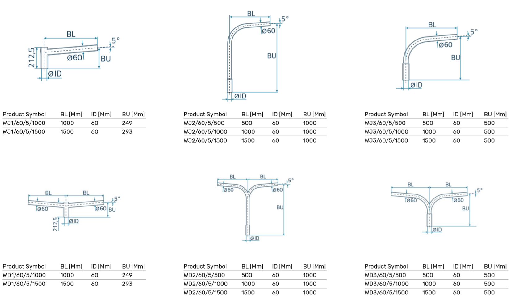
Standard concrete foundations

Single cable joints


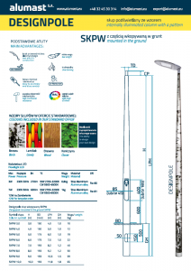
Poles with a pattern and internal illumination DESIGNPOLE
A basic composite column with high strength parameters. Complies with EN 40-7. Product is easy to assembly and economical in operation.
Advantages
- passive safety
- 100% recycling
- light construction
What is more
- it does not conduct electricity and has no scrap value
- resistant to pollution and weather conditions (including road salt and animal waste)
- modern design,
- height of columns from 3 to 12 meters
Application
- railway industry
- all types of roads
- parks, squares, streets
- energy industry
Choose a suitable option for you
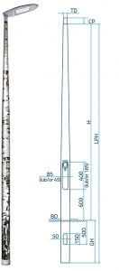
| Column Symbol | H [M] | BD [Mm] | LPH [M] | GH [M] | W [Kg] |
| SKPW 3,0/150/60 | 3 | 150 | 4 | 1 | 10 |
| SKPW 4,0/150/60 | 4 | 150 | 5 | 1 | 12 |
| SKPW 5,0/175/60 | 5 | 175 | 6 | 1 | 19 |
| SKPW 6,0/175/60 | 6 | 175 | 7 | 1 | 22 |
| SKPW 7,0/193/60 | 7 | 193 | 8,2 | 1,2 | 40 |
| SKPW 8,0/193/60 | 8 | 193 | 9,2 | 1,2 | 50 |
| SKPW 9,0/193/60 | 9 | 193 | 10,5 | 1,5 | 59 |
| SKPW 10,0/193/60 | 10 | 193 | 11,8 | 1,8 | 65 |
H [m] – height
BD [mm] – bottom diameter
LPH [m] – overall height
GH [m] – length of part in the ground
W [kg] – weight (without accessories)
Standard colours included in the offer

Wide range of RAL colors

Accessories
Aluminium brackets

Standard concrete foundations

Single cable joints

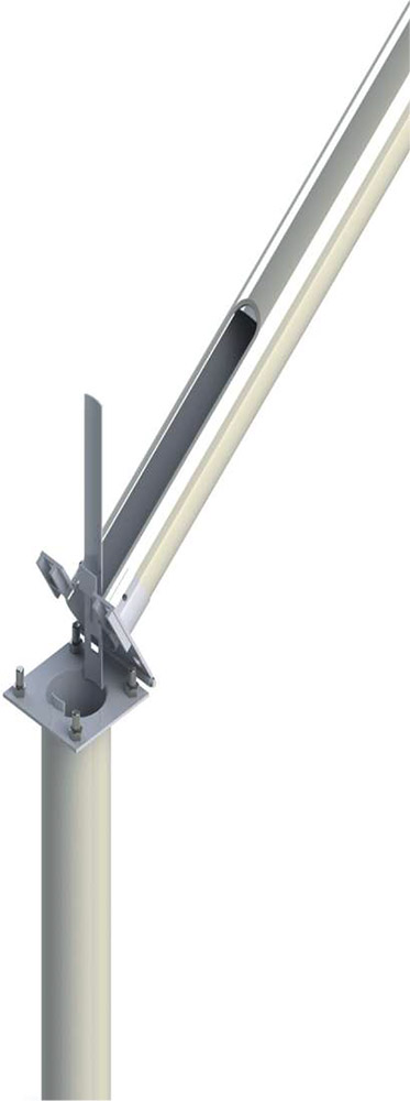
Poles with hinge mechanism EASYPOLE
Composite pole designed for use in hard-to-reach areas. Where there is no access for heavy vehicles with a lift, the ideal solution is a composite pole with a hinge mechanism (so-called hinged pole). It facilitates assembly, disassembly of the luminaire, replacement of the light source and other operating works.
EASYPOLE column is available in two versions: version STANDARD and version PREMIUM
Advantages
- non electric conduction
- light construction
- high mechanical resistance
What is more
- hinge mechanism which facilitates lowering of the pole when replacing the light
- source and maintenance of the luminaire,
- easy assembly and disassembly,
Application
- railway tractions
- ski slopes
- narrow roads
Choose a suitable option for you
SKPF-ŁP columns mounted on foundation

| PRODUCT SYMBOL | H [M] | BD [mm] | BD [mm] |
| SKPF-ŁP 4,0/175/60 | 4 | 175 | 200 |
| SKPF-ŁP 5,0/175/60 | 5 | 175 | 200 |
| SKPF-ŁP 6,0/175/60 | 6 | 175 | 200 |
| SKPF-ŁP 7,0/193/60 | 6 | 193 | 300 |
| SKPF-ŁP 8,0/193/60 | 8 | 193 | 300 |
| SKPF-ŁP 9,0/193/60 | 9 | 193 | 300 |
It is possible to manufacture poles with non-standard parameters at the customer’s request.
Possibility to reinforce the pole for dicult operating conditions.
H [m] – height
BD [mm] – bottom diameter
BPHD[mm]- bolt spacing
SKPW-ŁP Poles with a part dug into the ground
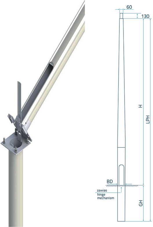
| COLUMN SYMBOL | H [M] | BD [mm] | LPH [m] | GH [m] |
| SKPW-ŁP 4,0/175/60 | 4 | 175 | 5 | 1 |
| SKPW-ŁP 5,0/175/60 | 5 | 175 | 6 | 1 |
| SKPW-ŁP 6,0/175/60 | 6 | 175 | 7 | 1 |
| SKPW-ŁP 7,0/193/60 | 6 | 193 | 8,2 | 1,2 |
| SKPW-ŁP 8,0/193/60 | 8 | 193 | 9,2 | 1,2 |
| SKPW-ŁP 9,0/193/60 | 9 | 193 | 10,5 | 1,2 |
It is possible to manufacture poles with non-standard parameters at the customer’s request.
Possibility to reinforce the pole for dicult operating conditions.
H [m] – height
BD [mm] – bottom diameter
LPH[m]- overall height
GH[m]- length of part in the ground
Standard colours included in the offer

Wide range of RAL colors

Accessories
Aluminium brackets

Standard concrete foundations

Single cable joints


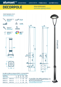
Stylised pole DECORPOLE
A line of innovative composite and aluminum poles perfectly suited to elegant, stylisedspaces. Thanks to the decorative base poles have a decorative function, emphasising the character and increasing the attractiveness of the surrounding.
Advantages
- elegant design
- no scrap value
- lightconstruction
What is more
- resistant to pollution
- it blends in perfectly with stylish, small architecture
- safe and economical maintenance
Application
- HoReCa
- developers
- parks, squares, streets
- mansion objects
Check additional solutions
- Possibility to choose a column made of composite or aluminum with a composite base
- LED strips illuminating the base, improve the visibility and fulfil the decorative function
- bases of columns can also play the role of road posts
- possibility to produce pole in any colour according to the RAL palette
Choose a variant for yourself
DECORPOLE stylised composite lighting column mounted in the ground SKPW-ST and mounted on foundation SKPF-ST
| Column Symbol | H (M) | TD (Mm) | CP (Mm) | LPH (M) | GH (M) | BPL (Mm) | BPT (Mm) | BPHD(Mm) | W (Kg) |
| SKPW-ST 3,0 SKPF-ST 3,0 |
3 | 60 | 130 | 4 | 1 | 260 | 8 | 200 | 10 |
| SKPW-ST 4,0 SKPF-ST 4,0 |
4 | 60 | 130 | 5 | 1 | 260 | 8 | 200 | 12 |
| SKPW-ST 5,0 SKPF-ST 5,0 |
5 | 60 | 130 | 6 | 1 | 260 | 8 | 200 | 19 |
At the customer’s request, it is possible to produce columns with non-standard parameters. Possibility to strengthen the pole for difficult operating conditions.


Safe poles PASSIVEPOLE
Safe composite column with high strength parameters. Complies with EN 40-7 and EN 12767.
Certificate confirms the passive safety of composite poles in the category of non-energy absorbing constructions (NE) for a crash speed of 70 km / h with safety level 2.
70, NE, 2
Advantages
- passive safety
- 100% recyclable
- lightweight construction
What is more
- it does not conduct electricity, it has no scrap value
- resistant to pollution and weather conditions (including road salt and animal waste)
- modern design,
- height of columns from 5 to 22 meters
Application
- all types of roads
Choose a variant for yourself
Mounted on the foundation

| Column Symbol | H [M] | BD [Mm] | BPHD [Mm] | W [Kg] |
| SKPF-P 7,0/70NE2 | 7 | 193 | 300 | 55 |
| SKPF-P 8,0/70NE2 | 8 | 193 | 300 | 60 |
| SKPF-P 9,0/70NE2 | 9 | 193 | 300 | 70 |
Standard colours included in the offer

Wide range of RAL colors

Accessories
Aluminium brackets

Standard concrete foundations

Single cable joints


Multimedia lighting poles SMARTPOLE MULTI
Ligh ting column does not have to be just a construction supporting luminaire. The range of possibilities for additional equipment of multimedia poles is very wide and depends on the needs and characteristics of the place and the environment.
Advantages
- mobile and multimedia solutions
- low CO2 emission
- increased security
- wireless lighting management
- 100% recycling
- light construction
Additional possibilities
- wireless Internet access (Wi-Fi)
- interactiveand educational games
- wireless inductive charging of portable devices
- broadcasting ads
- integration with mobile applications
- gathering anonymous data on traffic
- the ability to configure additional solutions in accordance with the project requirements
Application
- railways
- recreational facilities
- parks, squares, streets
- commercial facilities

Active pole on pedestrian crossings SMARTPOLE CROSSING
How to eectively care for safety and improve the quality of life in a modern environment? The answer to this question is brought by both advanced and innovative technologies as well as the improvement of everyday well-known solutions. The result of combining these two elements is the SMARTPOLE CROSSING. These are active poles, caring for the level of safety of road trac participants in the most critical points, such as pedestrian crossings.
Advantages
- non electrical conduction
- low CO2 emission
- increased security
What is more
- excellent lighting for pedestrian crossings
- curtain motion sensor within crossing
- a luminous driver warning system about the presence of pedestrians
- audio warning messages for pedestrians
Application
- pedestrian crossings
- all categories of roads
Why it is worth
- SMARTPOLE solutions improve the concentration of pedestrians and drivers
- increase the safety and visibility of pedestrian crossings
- positively aect the flow of traffic
- they help people with disabilities, the elderly and children
Choose a suitable option for you
Autonomous version mounted in the ground

Autonomous version mounted on foundation

Standard colours included in the offer

Wide range of RAL colors

Accessories

LED luminaire with an asymmetrical light distribution enabling the creation of a contrast and lighting of the pedestrian’s silhouette. With such type of luminaires, the phenomenon of driver glare does not occur. It is possible to use dierent color temperatures:
– white – cold
– white – neutral
– white – warm
Power from 59 to 109W

9 yellow LED lights placed inside the pole

A loudspeakerthat plays recorded warnings and educational messages, power of 20W RMS and high eciency; resistant to weather conditions.

A curtain motion sensor detecting people at the pedestrian crossing (it is possible to adapt it to every pedestrian crossing)

D6 road sign (possibility of mounting other road signs with or without illumination)

Pole SMARTPOLE CHARGER with electric vehicles charging station
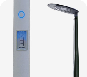
Electric vehicles charging station SMARTPOLE CHARGER Combines charging and street lighting.
Car charging station for applications in an urban environment. Intended for installation on public parking lots, in front oces, hotel and industrial facilities as well as in parking bays along streets. Ideal for installation in lighting points on the principle of replacing the old column on the composite column with the charger SMARTPOLE. Thanks to such a solution, you do not need to install additional devices.
Advantages
- mobile and multimedia solutions
- low CO2 emission
- safety
- bezprzewodowe zarządzanie oświetleniem
- 100% recycling
- low construction
Additional possibilities
- car charging while ensuring illumination
- easy service – automatic electronic switch on and shut o, client application or website
- full safety – composite is an insulator
- resistance to external factors and acts of vandalism – charger is mounted inside the column
- lighting columns as an optimal charging location (parkings, staging points)
- possibility of fast and eective extension of charging network using existing energy grid – installation of charging station by replacement of existing column
- respect of urban space – there is no need to instal additional devices
- the ability to configure additional options such as wireless internet (WI – FI), motions sensors etc.
- additonal power allocation is not needed
Application
- hotels
- recreational facilities
- parks,
- squares, alleys
- commercial facilities

Lightning protection masts STORMPOLE
Product is easy to assembly and economical in operation.
Advantages
- passive safety
- 100% recycling
- light construction
What is more
- it does not conduct electricity, it has no scrap value
- resistant to pollution and weather conditions (including road salt and animal waste)
- modern design
- height of masts from 5 to 22 meters
Application
- railway industry
- all types of roads
- parks, squares, streets
- energy industry
Choose a suitable option for you

| Column Symbol | H [M] | BD [Mm] |
| SKPW-OD 5,0/120/65 | 5 | 120 |
| SKPW-OD 6,0/120/65 | 6 | 120 |
| SKPW-OD 7,0/120/65 | 7 | 120 |
| SKPW-OD 8,0/120/65 | 8 | 120 |
| SKPW-OD 9,0/120/65 | 9 | 120 |
| SKPW-OD 10,0/140/65 | 10 | 140 |
| SKPW-OD 11,0/140/65 | 11 | 140 |
| SKPW-OD 12,0/140/65 | 12 | 140 |
| SKPW-OD 13,0/175/65 | 13 | 175 |
| SKPW-OD 14,0/175/65 | 14 | 175 |
| SKPW-OD 15,0/175/65 | 15 | 175 |
| SKPW-OD 16,0/175/65 | 16 | 175 |
| SKPW-OD 17,0/175/65 | 17 | 175 |
| SKPW-OD 18,0/200/65 | 18 | 200 |
| SKPW-OD 19,0/200/65 | 19 | 200 |
| SKPW-OD 20,0/200/65 | 20 | 200 |
H [m] – height of the column
BD [mm] – bottom diameter
Wide range of RAL colors


Telecommunication supports
Composite telecommunication poles for the construction of fiber optic lines as an alternative to wooden and concrete poles. Composite poles, thanks to their advantages, and in particular low weight, significantly reduce the cost of the entire investment.
Advantages
- light construction
- no operating costs
- 40 years of column lifespan
What is more
- assembly without using heavy equipment
- possible manual transfer of poles in dicult terrain
- one truck = 300 composite poles
Application
- telecommunication
- fiber-optic networks
Choose a suitable option for you

| LPH [M] | Apical Force KN | BD [Mm] | TD [Mm] | GH [Mm] |
| 7 | 0,3 | 140 | 110 | 1,2 |
| 8,5 | 0,3 | 165 | 120 | 1,2 |
| 10 | 0,3 | 165 | 120 | 1,5 |
| 7 | 0,7 | 140 | 110 | 1,2 |
| 8,5 | 0,7 | 165 | 120 | 1,2 |
| 10 | 0,7 | 193 | 140 | 1,5 |
| 7 | 1,6 | 165 | 120 | 1,2 |
| 8,5 | 1,6 | 165 | 120 | 1,2 |
| 10 | 1,6 | 193 | 140 | 1,5 |
Standard colours included in the offer

Ral 7035
Wide range of RAL colors

Alumast еnergy poles

Core composite Eco
The composite rod, apart from the unprecedented lightness combined with durability, are a full insulator, which will eliminate the use of a hoop.
Due to the fact that the composite poles are made of polyester-glass composite, they are characterized by:
- durability – the pole is resistant to road salt and other means used to clear snow from roads, traffic pollution, animal urine, bark beetles and woodpeckers; there is no problem with dew point, icing, flooding of wires inside the pole. It does not soak, does not break or break. The composite rod is elastic and resilient – the yield point disappears, at which permanent deformation occurs, and the exceeded tip force does not cause deformation of the column.
- safety – the production of the pole is ecological and the pole is 100% recyclable. The resistance of the rod to UV rays and low and high temperatures is the result of the use of appropriate materials for its production. Flammability tests have shown that the composite is a flame-retardant and vandal-resistant material. The Eko composite rod meets the requirements of PN-EN 1317 regarding passive safety, which is so important in recent times. In a collision, the pole absorbs energy only to a small extent – the vehicle continues to travel after the collision, but at a reduced speed. Research has shown that the ASI index – acceleration intensity, in accordance with PN-EN 1317, is five times lower than in the case when the effects of a collision are dangerous or fatal for the people in the vehicle. The rod is made of polyester-glass composite, which is why it is an insulator.
- low maintenance cost – The Eko composite rod is an ultra-light product (for a height of 9 m and a tip force of 2.5 kN, the weight is only about 60 kg), easy to transport and assemble. Installation does not require the use of a crane. Two fitters can set up a pole in a short time. The advantage is the fact that the pole can be installed not only in forest, mountainous areas with difficult access, but also in built-up areas. In addition, the composite is not a scrap value, so there are no additional costs related to the theft of the rod elements. The fact that the composite is an insulator means that periodic insulation tests are unnecessary.
More advantages of the composite wire can be found in the COMPOSITE tab
The EKO composite rod is manufactured in the same technology as the composite lighting pole, which obtained the Certificate of Conformity (CE) with the European standard PN-EN 40-7. Their design and production are carried out in accordance with the standards of the ISO 9001: 2008 quality management system.
ECO RODS TABLES
| Pole symbol | Apical strength | length | Ø basis | Ø top | weight | colour | |
|---|---|---|---|---|---|---|---|
| 1 | Eko 9/2,5 | 2,5 kN | 9 m | 193 mm | 150 mm | 60 kg | biały |
| 2 | Eko 9/4,5 | 4,5 kN | 9 m | 193 mm | 150 mm | 80 kg | niebieski |
| 3 | Eko 9/6 | 6 kN | 9 m | 220 mm | 173 mm | 80 kg | czarny |
| 4 | Eko 9/10 słupy kratowe | 10 kN | 9 m | czerwony | |||
| 5 | Eko10,59/2,5 | 2,5 kN | 10,5 m | 193 mm | 150 mm | 70 kg | biały |
| 6* | Eko 10,5/4,5 | 4,5 kN | 10,5 m | 193 mm | 150 mm | 100 kg | niebieski |
| 7 | Eko 10,5/6 | 6 kN | 10,5 m | 250 mm | 173 mm | 100 kg | czarny |
| 8 | Eko 10,5/10 słupy kratowe | 10 kN | 10,5 m | czerwony | |||
| 9 | Eko 12/2,5 | 2,5 kN | 12 m | 220 mm | 173 mm | 100 kg | biały |
| 10 | Eko 12/4,5 | 4,5 kN | 12 m | 250 mm | 173 mm | 120 kg | niebieski |
| 11 | Eko 12/6 | 6 kN | 12 m | 250 mm | 218 mm | 120 kg | czarny |
| 12 | Eko 12/10 słupy kratowe | 10 kN | 12 m | czerwony |
POLE ARMOR
- ROD DIGGED INTO THE GROUND – foundation without additional supporting elements; a column inserted into a drilled hole and filled with native soil
- FOUNDATION UI (with the U-85K plate) – the U-85K floor plate is a replacement for the U-85 type standing plate, made of a light and very durable composite, combining the simplicity of the U-85 standing plate, lightness and several times greater strength than a traditional concrete slab


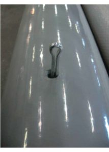

Service pole
The service power pole is used during the modernization of the line. It is used “pole for pole”. The great advantage of these poles is that they can be stored in any energy area. Power can be restored temporarily when no special equipment is involved. This can be done by the crew of the energy emergency.
OPTION – 2-SEGMENT ENERGY SERVICE POST
Diagram of the bypass as an ad hoc method during modernization, bringing measurable benefits for the LV line operator

SERVICE ENERGY POLE WITH AN EXHAUST – FUNCTIONAL ON THE BASIS

SERVICE ENERGY POST
The order of placing the service pole:
- Place the support on the ground and level it, selecting the ground under it until the maximum contact with the ground is obtained (do not sprinkle it);
- Put one layer of the standing boards on the base;
- Screw the carrying bolts and the plate to the base as shown in the drawing No. 1;
- Assemble the service pole as a whole by pressing the pin fi 8 in the hole to block both segments in the middle and connect the pole with the bottom plate of the bracket using the hinge pin;
- Place the service pole in a vertical position, setting it in a vertical position using the nuts on the carrying bolts;
- Lock the bolt connection by tightening the nuts with the torque shown in the figure;
- Place the remaining 5 layers of the standing boards on the load-bearing base.
ATTENTION! The service power pole will be able to transfer the load with the assumed bending moment under the following conditions:
- The strength of the soil under the stall will be equal to or greater than 31.8 kN / m2
- The stall will be loaded with six layers of siding plates, each 600x850x60mm
- The outer dimensions of the base of the parking lot will be 1530x1530mm
POST BASE PLAN
Correction consisting in removing or adding plates is unacceptable.


Strengthened column Eko-Sz
Eko-Sz reinforced composite poles complete the offer of supporting structures for the construction of overhead lines. These are poles reinforced with polyurethane foam, suitable for mounting in stilts.
TABLE OF POLES Eko-Sz
| Pole symbol | Apical strength | length | Ø basis | Ø top | colour | ||
|---|---|---|---|---|---|---|---|
| 1 | Eko-Sz 10,5/4,5 | 4,5 kN | 10,5 m | 250 mm | 173 mm | blue | |
| 2 | Eko-Sz 10,5/6 | 6 kN | 10,5 m | 250 mm | 173 mm | black | |
| 3 | Eko-Sz 12/4,5 | 4,5 kN | 12 m | 250 mm | 173 mm | blue | |
| 4 | Eko-Sz 12/6 | 6 kN | 12 m | 250 mm | 218 mm | black |
OPTIONAL ARMAMENT OF THE POLE:
- construction for insulator;
- construction clamps;
- stilts.


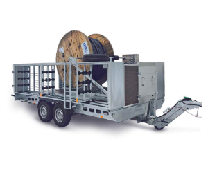
Mobile service line
The mobile service line is a complete solution to supply consumers during modernization works on the existing line or in the event of a breakdown. One of its main tasks is to minimize the need for interruptions in electricity supply. When there is a need to build a service line (so-called bypass), we have a ready set for its creation.
Advantages:
- a quick way to eliminate failure – easy installation,
- reduction of SAIDI and SAIFI indicators,
- lower power failure fees,
- poles that do not interfere with the ground – no formal and legal problems,
- cheaper in operation compared to the use of a power generator
Basic equipment:
- 10 holes for transporting 10 pcs. service poles and service bases;
- haul-off box;
- lighting retractable mast;
- service cable winch with a cleaning system extending the service life of the cable;
- electrical socket boxes for MV connectors
Additional elements of equipment (possibility of individual selection of elements for the basic version):
- composite service poles;
- service pole lattice base;
- reusable ENSTO cable in accordance with PN-HD 620 S2: 2010E;
- generator;
- accessories for service poles.
Take advantage of the possibility of external financing through subsidies from European funds or national programs up to 70% of the value and enjoy the benefits of the MOBILE SERVICE LINE! Additionally, you can take advantage of the leasing offer for a MOBILE SERVICE LINE.
See the movie how the MOBILE SERVICE LINE works
Download catalogs
Emiter polyester panel catalogs
Alumast composite supports and posts
Good to know
Security categories. IP and IK codes
IP codes
(degree of protection)
| Description | |
|---|---|
| Protection against intrusion of solid foreign objects and acceptance into dangerous parts | The first digit |
| Unprotected | 0 |
| 50 mm diameter (hand) | 1 |
| 12.5 mm diameter (finger) | 2 |
| 2.5 mm diameter (tool) | 3 |
| 1.0 mm diameter (wire) | 4 |
| dust protection (cord) | 5 |
| dust resistance (cord) | 6 |
| Description | |
|---|---|
| Protection against water penetration | The second digit |
| Unprotected | 0 |
| Vertical dripping | 1 |
| Dripping (15 ° tilt) | 2 |
| Spraying | 3 |
| Splashing | 4 |
| Strong current | 5 |
| Very strong current | 6 |
| Short immersion | 7 |
| Continuous immersion | 8 |
| High pressure and temperature spraying from above | 9K |
Additional letters (A, B, C, D, H, S, W)
| Letters at the end of the IP code | Protection of persons from access to dangerous parts |
|---|---|
| – | There is no protection |
| A | Arm top |
| B | Finger |
| C | The diameter of the tool is 2.5 mm |
| D | Wire diameter 1 mm, length 100 mm |
| H | High voltage device |
| S | Movement during water tests |
| W | Weather conditions |
IK codes – impact protection
(IK code characterizes the ability of the equipment to resist mechanical impact on all sides (EN 50102))
| IK | Impact energy [J] | Hammer mass [kg] | Height of hammer elevation [cm] |
|---|---|---|---|
| 0 | 0 | – | – |
| 1 | 0,15 | 0,2 | 7,5 |
| 2 | 0,2 | 0,2 | 10 |
| 3 | 0,35 | 0,2 | 17,5 |
| 4 | 0,5 | 0,2 | 25 |
| 5 | 0,7 | 0,2 | 35 |
| 6 | 1 | 0,5 | 20 |
| 7 | 2 | 0,5 | 40 |
| 8 | 5 | 1,7 | 29,5 |
| 9 | 10 | 5 | 20 |
| 10 | 20 | 5 | 40 |
Mechanical tests
Mechanical tests
Flammability and impact test
Checking the resistance by throwing the spike at the front of the panel
Checking the resistance by throwing the spike into the side of the panel
Checking the resistance by throwing a sandbag into the panel
Checking the resistance by throwing the ball into the panel
Security
The manufacturer of switchgear EMITER aims to provide consumers not only with quality but also with safe products. As a result, the company’s products passed the short-circuit resistance test performed by the electrical testing laboratory RWE Eurotest GmbH (Germany, 2007). The study was commissioned by EO.N.
Aim of the test: to verify the strength and safety of the panel in the event of a short circuit.
Test method: 10kA current 0.5s short circuit.
Result:


Test video:
Humidity control
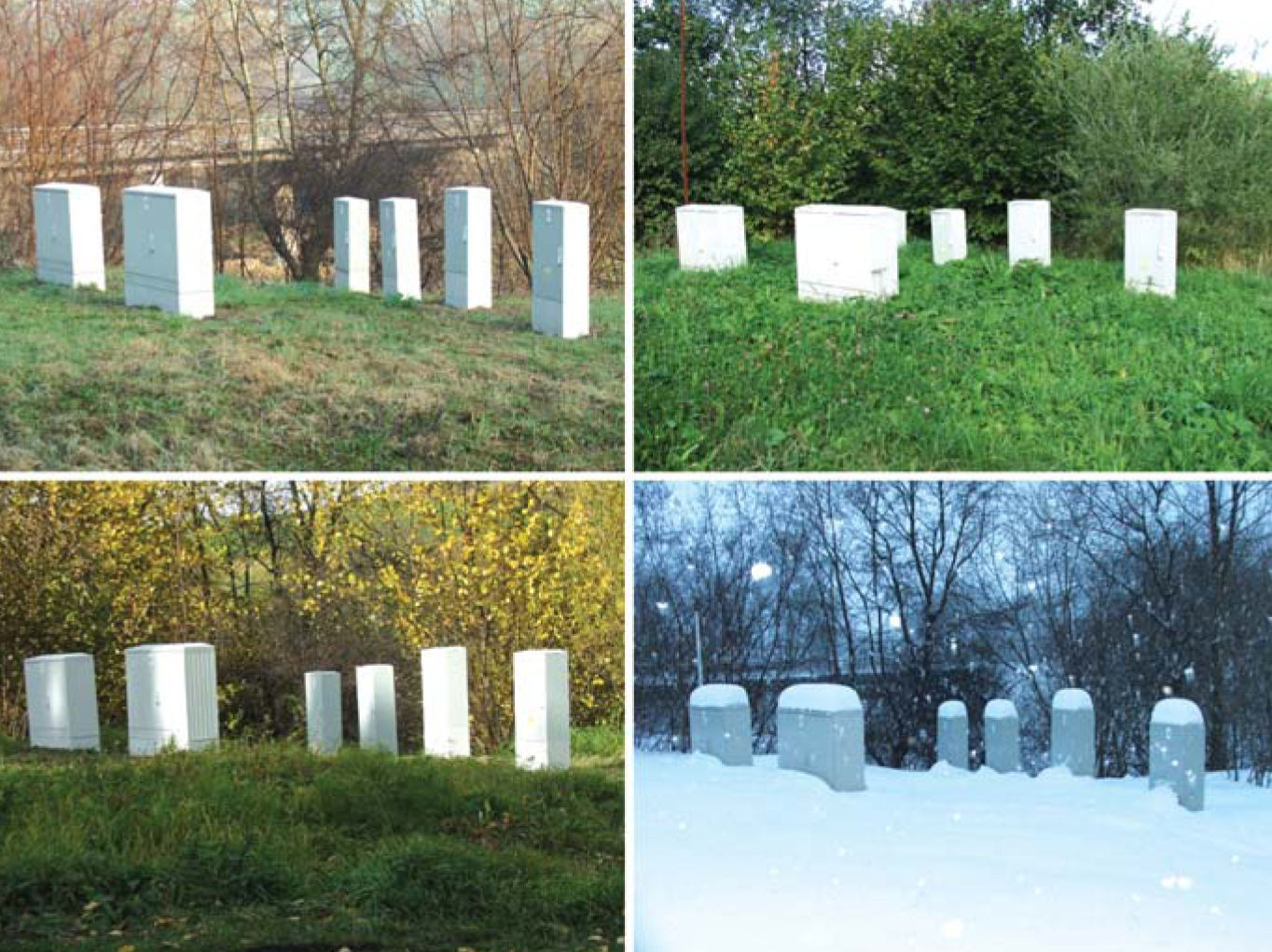
The conditions of air temperature change, which are so characteristic of the Lithuanian climate, are very favorable for the increase of the humidity level in closed cavities. This phenomenon also affects free-standing switchgear, where it is particularly undesirable.
Addressing this issue throughout 2006. A number of studies were carried out in the territory of EMITER, on the basis of the results of which a method was developed for the effective reduction of humidity in the above-mentioned facilities.
Here are photos showing the occurrence of moisture inside the panel:

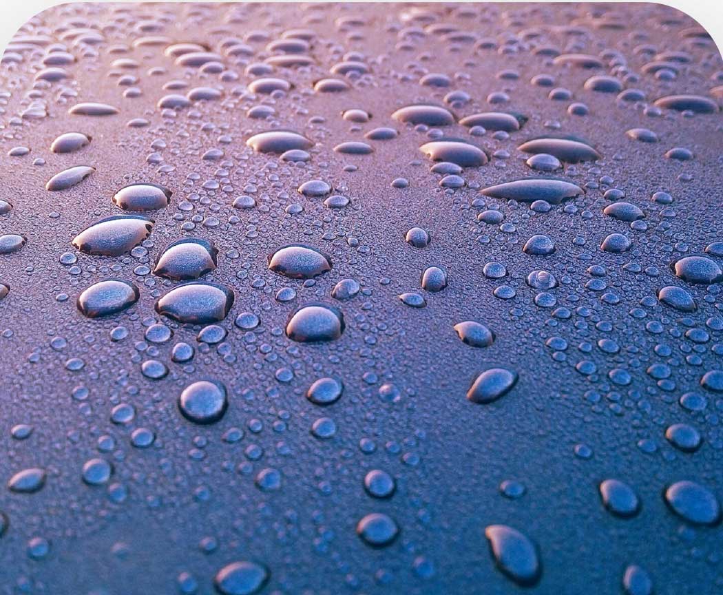
Moisture inside the switchgear is caused by condensation of vapors – at higher temperatures there are more of them, and as the temperature drops, water droplets appear on the walls of the electrical equipment. This phenomenon is exacerbated during the autumn-winter season. Condensation in the panels is a serious problem to which one cannot remain indifferent. It can cause the unit to malfunction, corrode, and even crash. All of this is closely related to the safety of those around you.
Tests have shown that the device must be properly installed in the floor to avoid this. To date, the biggest mistake installers have made is leaving empty space in the foundation. After filling it with earth, it is really necessary to remember about the internal filling with a special material.
EMITER has been producing such a filler in the form of granules for several years. This material effectively prevents the formation of moisture, fills the empty space in the panel and, as a result, reduces the likelihood of condensation. When using this method, it is mandatory to take into account the instructions adapted to the different types and sizes of foundations.

Flammability of products
Switchgear is usually installed in easily accessible locations and buildings, so many who are interested in such products are concerned about their safety and fire resistance. That is why in this section we present the properties of the special material (SMC) from which our partner EMITER panels are made and their proof of fire resistance.
EMITER plastic panels are made of thermosetting material consisting of polyester and various additives designed to improve certain properties of the product – ease of processing, plasticity, mechanical resistance, fire resistance, etc. In addition to components such as polyester, resin, fiberglass and other fillers, they contain a so-called “fire extinguisher”. It has a significant effect on the flammability of the product as it melts the spread of flame. This definitely increases the cost of the final product, but at the same time ensures much higher operational safety. One of the most important facts is that during combustion, these products do not emit burning drops, which is typical of thermoplastic products. This significantly reduces the risk of fires.

Fig. 1 (a) view of the transformer station; (b) transformer at the time of the accident; (c) post-extinguishing image: one burned-out cabinet and a VIT-compliant EMITER cabinet (marked with an arrow).
Flammability tests
In practice, several methods are known for checking the flammability of plastic materials: V – vertical, and HB and FH – horizontal flammability tests. Their descriptions can be found in the European standard and the American standard UL94, which is, among other things, more detailed and stricter.
During the tests, the flammability categories are ranked according to the level of severity (starting from the highest): 5VA, 5VB, V0, V1, V2 and HB = FH. As 5VA and 5VB are not used for the labeling of plastic materials, an overview of them will not be provided further.
In order to be able to compare the results of different tests, the samples used must be identical. Therefore, in the studies described below, their dimensions (125×13 mm) and burner force (50W) are the same in each of the above methods. Although it is known from the laws of physics that the thicker the sample, the more energy it will take to ignite it, PN-EN 60695-11-10 does not define the value of this parameter, but only provides a maximum of 13 mm.
V – vertical combustion test according to PN-EN 60695
10 pre-stabilized samples are used in this test (5 samples were tested in a 7-day thermal aging test at 70C and in a 5- to 48-hour test at 23C). A properly prepared sample is placed in the holder fi so that its longitudinal axis is vertical (Figure 2) and cotton wool is placed 30 cm below. A burner is then added so that its flame is in the center of the lower edge of the sample and the edge of the burner is 10 mm from the test substance.
The flame must touch the sample for 10s. If drops of molten material are emitted during the test, the burner must be tilted at an angle of 45 blades to prevent dripping. After 10 s, ignite the flame and record the burning time of the material (t1). As soon as the flame is extinguished, the burner is again placed under the sample for 10 s and the burning time (t2) and the burning time of the material after the final firing (t3) are measured in the same way. After the test, the total time for each of the samples is measured.
Test V – evaluation criteria
In summarizing the test, several criteria are used to describe the individual categories:
V0
- Burning time of a single sample: t1 + t2 ≤ 10s;
- Total burning time of all samples for each of the stabilization methods: ≤ 50s;
- Burning and flame time of each sample after the burner was added a second time: t2 + t3 ≤ 30s;
- The flame did not reach the holder;
- The cotton gasket did not ignite from falling particles or drops.
V1
- Burning time of a single sample: t1 + t2 ≤ 30s;
- Total burning time of all samples for each of the stabilization methods: ≤ 250s;
- Burning and flame time of each sample after the burner was added a second time: t2 + t3 ≤ 60s;
- The flame did not reach the holder;
- The cotton gasket did not ignite from falling particles or drops.
V2
The first four criteria are identical to category V1, while the fifth criterion has a positive result, i. the cotton gasket ignites against falling particles or drops.
If the vertical combustion method fails to assess the flammability of substance V, the standard recommends testing its properties by the HB method.
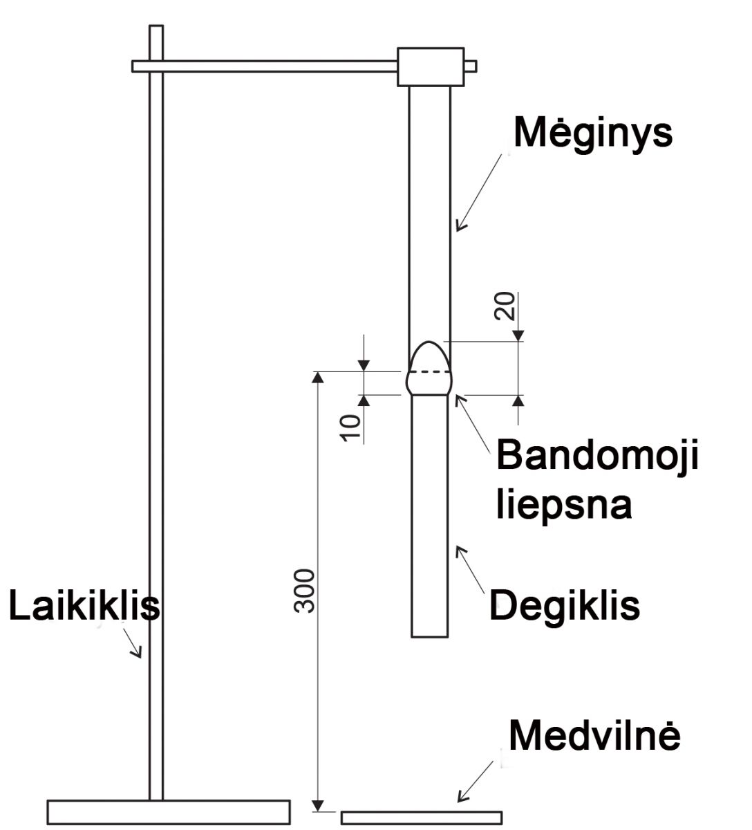
Fig. 2 Vertical combustion test according to PN-EN 60695
HB – horizontal combustion test according to PN-EN 60695
3 samples were used for the HB test, preceded by 48 h. stabilized at 23C. Mark a line on each of them at a distance of 25 and 100 mm from one end of the sample. The sample is then held in the holder fi so that its longitudinal axis is horizontal and its transverse axis is inclined at an angle of 45 degrees (Figure 3). The burner is positioned so that its principal axis is in the same vertical plane as the longitudinal axis of the sample.
If, during combustion, the flame does not exceed the limit of 25 mm (first line) before 30 s, the position of the test fire does not change and it is not drawn for that long. When the apex of the flame reaches the 25 mm mark, start measuring how long the sample burns or how long it takes for the flame to reach the 100 mm mark. In this way, all three samples mentioned above are tested.
HB test – evaluation criteria
Substances that pass the test are classified as HB40 and HB75. To be classified as HB40, they must meet one of the following criteria:
- After the fire has been drawn, the material must not burn with a visible flame;
- If the material burns even after the fire source has been drawn, the flame must not exceed the marked limit of 100 mm;
- If the flame exceeds the maximum specified limit, its burning rate must not exceed 40 mm / min.
The substance is classified as HB75 if the burning rate does not exceed 75 mm / min when the flame exceeds the maximum limit of 100 mm.

Fig. 3 Method of performing the HB test
FH – horizontal combustion test
The FH test procedure is identical to the HB test, and categories FH1, FH2 and FH3 are distinguished in the classification.
The evaluation criteria include:
- Length of the burnt part of the sample;
- Burning rate.
Summary
Looking at the problem of flammability of plastic materials, it is worth noting that flammable and flame-retardant materials are used in switchboard cabinets. We deliberately do not use the words “non-combustible material” because each substance is flammable and its rate and method of ignition depend only on the prevailing environmental factors (burning time, temperature, oxygen content, etc.).
The least stringent testing method is horizontal HB, which is recommended according to PN-EN 60439-5 (until 2007, previous publications of this standard required FB testing). The HB rate has relatively few requirements for test samples, making it difficult to speak of flammable materials in this case.
A suitable criterion for assessing the flammability of materials is criterion V – vertical combustion test. The flame formed at the bottom of the sample heats its entire surface, which is a much more realistic reflection of the operation of the junction box in the event of an accident (when a source of high temperature occurs and then a fire). This situation can occur when the screws that connect the conductive elements are loosened or, e.g. under conditions of internal arc discharge that generates a significant amount of heat.
As mentioned earlier, one of the components of a thermoset material is the “extinguisher”, which determines not only the degree of flammability of the material, but also the price. It is also known that most business partners follow it as a key criterion in public procurement, while the technical value of the product is in the background. Finally, compliance with the minimum standards is limited, although all energy products must pass the V0 flammability test with positive results before entering the market (especially in German, French and Czech energy).
In 2009, EMITER carried out comparative tests of three competitive products available on the Polish market. As the laboratory of this company is not accredited, the determination of the flammability criterion was entrusted to an independent team of German researchers. The summary report states that none of the samples met the prerequisites for V0. Only the requirements of FH2 were met: sample No 1 – FH2 / 20 mm, sample No 2 – FH2 / 10 mm and sample No 3 – FH2 / 11 mm. Meanwhile, EMITER products are made of a material that meets the standard V0 – the strictest according to PN-EN 60695-11-10 in Poland. To maintain this, the flammability properties of the material are constantly monitored in the company’s laboratory. Below are videos that clearly demonstrate the quality of EMITER products and the innovative use of SMC material.
Test No1. EMITER sample
Test No2. Analogue sample from another manufacturer
“Fire Pool” is another test of the flammability of the entire product
News

Contacts
| UAB “elPEAK”. Address: Ožkinių str. 75d, LT-08405, Vilnius Company code: 302442365 |
|
| Tel.: +370 679 88006 Email: info@elpeak.lt |
| Margus Rannamaa Adress: Kapteni tee 2, Soodevahe Rae vald, 75322 Harju maakond Estonia |
|
| Tel.: +372 504 5917 Email: margus@pegatron.ee |


